| 名 称: |
三一挖掘机SY750H维修手册2021版 |
| 编 号: |
2026060115282344 |
| 点击数: |
|
|
资料格式 |
|
资料大小 |
|
| 版本日期 |
|
资料语言 |
|
| 资料属性 |
|
推荐等级 |
★★★ |
| 资料类型 |
正常销售商品 |
发布时间 |
2026/6/1 15:15:14 |
| 降价折扣 |
折 |
限购数量 |
本 |
| 优惠期限 |
~ |
| 购物积分 |
0分 |
库存数量 |
本 |
| 赠送点券 |
0点 |
返还现金券 |
0 |
| 促销方案:不促销 |
| 资料价格:市场价:¥480/本 商城价:¥480/本 会员价:¥―/本 优惠价:¥480/本 |
  |
| 资料说明: |
三一挖掘机SY750H维修手册2021版
语言:英语
品牌:三一
机器类型:液压挖掘机
手册类型:服务手册、电气原理图、液压系统图
型号:三一SY750H挖掘机
发动机:五十铃AH-6WG1
出版日期:2021年
页数:588页
目录:
1 前言
1.1 服务手册的阅读方法
1.2 维护标准相关术语说明
1.3 电气元件与液压元件的处理方式
2 安全措施
2.1 安全标志使用说明
2.2 一般性通知
2.3 维护前的准备工作
2.4 维护/修理通知
2.5 其他通知
3 技术规格
3.1 规定尺寸
3.2 技术规格
3.3 重量对照表
3.4 发动机机油、燃油与冷却液
3.5 发动机的特性曲线
4. 结构、功能与维护标准
4.1 发动机与冷却系统
4.2 传动装置
4.3 下行装置
4.4 液压系统(第一部分)
4.5 液压系统,第二部分
4.6 液压系统,第三部分
4.7 工作装置
4.8 空调系统
4.9 发动机控制
4.10 电气控制系统
4.11 显示系统
5. 组件的标准数值
5.1 发动机相关部件的标准数值表
5.2 与车身相关部件的标准数值表
6 测试与调整
6.1 废气颜色的测量
6.2 调整阀门间隙
6.3 压缩压力的测量
6.4 注射时机的检查与调整
6.5 发动机油压的测量
6.6 发动机转速传感器的调整
6.7 制冷压缩机皮带张紧装置的检查与调整
6.8 旋转支撑轴承的间隙测量
6.9 行走机构拉紧装置的检查与调整
6.10 对工作装置、回转装置及行走装置的液压油路中的液压压力进行检测与调整
6.11 控制油路压力的检查与调整
6.12 电磁阀输出压力的测量
6.13 先导阀输出压力的测量
6.14 工作装置的调整与回转PPC阀的调节
6.15 对作业装置液压系统沉降情况的检查
6.16 排放液压油管路中的剩余压力
6.17 油液泄漏量的测量
6.18 所有设备的放气操作
6.19 传感器的检测
7. 故障诊断与排除
7.1 故障诊断时的注意事项
7.2 故障诊断前的检查
7.3 故障诊断的类别与步骤
7.4 连接器
7.5 当显示当前故障代码时的故障诊断方法
7.6 电气系统的故障诊断(模式E)
7.7 液压与机械系统的故障诊断方法
8. 拆卸与组装
8.1 运营相关通知
8.2 启动电机总成的拆卸与安装
8.3 燃油喷射泵总成的拆卸与安装
8.4 发动机后油封的拆卸与安装
8.5 气缸盖总成的拆卸与安装
8.6 气缸盖总成的拆卸与组装
8.7 散热器组件的拆卸与安装
8.8 发动机及液压泵装置的拆卸与安装
8.9 最终传动装置的拆卸与安装
8.10 最终传动装置的拆装
8.11 旋转电机及旋转机构组件的拆卸与安装
8.12 旋转电机及旋转机构的拆卸与组装
8.13 导轮装置的拆卸与组装
8.14 链轮的拆卸与安装
8.15 履带装置的拆卸与安装
8.16 后回转轴承装置的拆卸与安装
8.17 旋转台的拆卸与安装
8.18 中央回转接头组件的拆卸与安装
8.19 中央后回转接头组件的拆卸与组装
8.20 液压油箱总成的拆卸与安装
8.21 控制阀组件的拆卸与安装
8.22 液压泵组件的拆卸与安装
8.23 液压泵输入轴上油封的拆卸与安装
8.24 独立式油雾分离器的拆卸与安装
8.25 工作装置先导阀组件的拆卸与组装
8.26 行走先导阀组件的拆卸与组装
8.27 液压缸组件的拆卸与组装
8.28 工作装置的拆卸与安装
8.29 空调设备的拆卸与安装
8.30 平衡重组件的拆卸与安装
8.31 驾驶室组件的拆卸与安装
8.32 显示屏的拆卸与安装
8.33 控制器组件的拆卸与安装
8.34 无线电设备的拆卸与安装
8.35 蓄电池的拆卸与安装
8.36 钮匙开关的拆卸与安装
8.37 保险盒的拆卸与安装
8.38 擦窗器的拆卸与安装
8.39 继电器的拆卸与安装
8.40 插入式部件端子的安装与拆卸方法
9 液压与电气系统图
9.1 符号说明
9.2 启动与预热控制
9.3 辅助功能控制
9.4 CAN通信
9.5 辅助功能控制2
9.6 主控制器
9.7 主控制器2
9.8 辅助控制器
9.9 显示效果
9.10 发动机控制器
9.11交流控制装置
9.12 保险丝盒
9.13 汽车线束组件
9.14 控制开关线束
9.15 工具箱固定装置
9.16 泵室连接装置
9.17 车身固定装置
9.18 身体固定装置
9.19 液压系统示意图
Sany Excavator SY750H Service Manual 2021
Size: 57.83 MB
Format: PDF
Language: English
Brand: Sany
Type of Machine: Hydraulic Excavator
Type of Manual: Service Manual, Electrical Diagram, Hydraulic Diagram
Model: Sany SY750H Excavator
Engine: Isuzu AH-6WG1
Publication Date: 2021
Number of Pages: 588 Pages
Contents:
1 Preface
1.1 Reading Method of Service Manual
1.2 Explanation on Terms for Maintenance Standards
1.3 Handling of Electrical Component and Hydraulic Components
2 Safety
2.1 Instructions on Safety Signs
2.2 General Notices
2.3 Preparatory Work before Maintenance
2.4 Notices for Maintenance/Repair
2.5 Other Notices
3 Technical Specification
3.1 Specified size
3.2 Technical Specification
3.3 Table of Weight
3.4 Engine oil, fuel and coolant
3.5 Feature curve of engine
4 Structure, function and maintenance standard
4.1 Engine and Cooling System
4.2 Transmission Train
4.3 Lower travelling device
4.4 Hydraulic system (Part 1)
4.5 Hydraulic system, Part 2
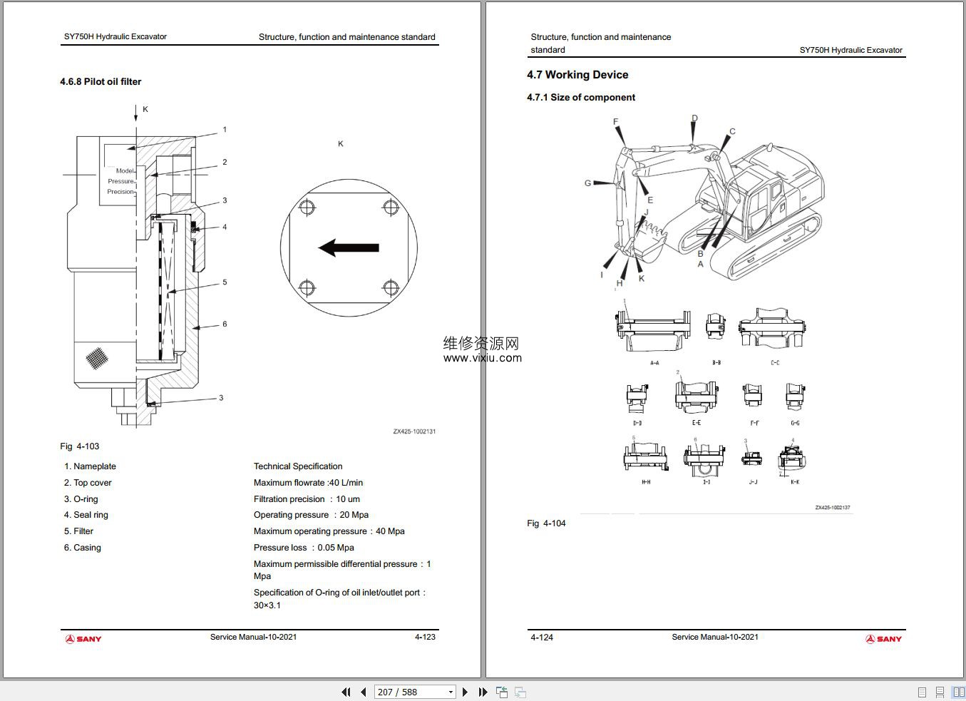
4.6 Hydraulic system, Part 3
4.7 Working Device
4.8 Air conditioning system
4.9 Engine control
4.10 Electrical Control System
4.11 Display system
5 Standard value of components
5.1 Table of standard values for engine-related parts
5.2 Table for standard value of body-related parts
6 Testing and Adjustment
6.1 Measurement of Color of Exhaust Gas
6.2 Adjust the valve clearance
6.3 Measurement of compression pressure
6.4 Inspection and adjustment of injection timing
6.5 Measurement of engine oil pressure
6.6 Adjustment of engine speed sensor
6.7 Inspection and adjustment of A/C compressor belt tensioning device
6.8 Measurement of clearance of slewing support bearing
6.9 Inspection and adjustment of crawler plate tensioning device
6.10 Inspection and adjustment of hydraulic pressure in hydraulic oil ways for working device, slewing and travelling
6.11 Inspection and adjustment of control oil way pressure
6.12 Measurement of output pressure of electromagnetic valve
6.13 Measurement of output pressure of pilot valve
6.14 Adjustment of working device and slewing PPC valve
6.15 Inspection of hydraulic settlement of working device
6.16 Release of residual pressure in hydraulic oil way
6.17 Measurement of oil leakage
6.18 Air Bleeding for Every Device
6.19 Inspection on sensor
7 Trouble diagnosis and troubleshooting
7.1 Precautions during Trouble Diagnosis
7.2 Inspection before Trouble Diagnosis
7.3 Category and steps of trouble diagnosis
7.4 Connector
7.5 Trouble diagnosis when current trouble code is displayed
7.6 Trouble Diagnosis for Electrical System (Mode E)
7.7 Trouble diagnosis for hydraulic and mechanical systems (mode
8 Disassembling and Assembling
8.1 Notices for Operation
8.2 Dismantlement and installation of start motor assembly
8.3 Dismantlement and installation of fuel injection pump assembly
8.4 Dismantlement and installation of rear oil seal of engine
8.5 Dismantlement and installation of cylinder head assembly
8.6 Disassembling and assembling of cylinder head assembly
8.7 Dismantlement and installation of radiator assembly
8.8 Dismantlement and installation of engine and hydraulic pump assembly
8.9 Dismantlement and installation of final transmission assembly
8.10 Disassembling and assembling of final transmission assembly
8.11 Dismantlement and installation of slewing motor and slewing mechanism assembly
8.12 Disassembling and assembling of slewing motor and slewing mechanism assembly
8.13 Disassembling and assembling of guiding wheel assembly
8.14 Dismantlement and installation of sprocket
8.15 Dismantlement and installation of crawler assembly
8.16 Dismantlement and Installation of Back slewing Bearing Assembly
8.17 Dismantlement and installation of slewing table assembly
8.18 Dismantlement and installation of central slewing joint assembly
8.19 Disassembling and assembling of Central Back slewing Joint Assembly
8.20 Dismantlement and Installation of Hydraulic Oil Tank Assembly
8.21 Dismantlement and Installation of Control Valve Assembly
8.22 Dismantlement and installation of hydraulic pump assembly
8.23 Dismantlement and installation of oil seal in hydraulic pump input shaft
8.24 Dismantlement and installation of independent oil disperser
8.25 Disassembling and assembling of working device pilot valve assembly
8.26 Disassembling and assembling of travelling pilot valve assembly
8.27 Disassembling and assembling of hydraulic cylinder assembly
8.28 Dismantlement and Installation of Working Device Assembly
8.29 Dismantlement and installation of A/C device assembly
8.30 Dismantlement and installation of balance weight assembly
8.31 Dismantlement and installation of cab assembly
8.32 Dismantlement and installation of display screen
8.33 Dismantlement and installation of controller assembly
8.34 Dismantlement and installation of radio
8.35 Removal and Installation of Storage Battery
8.36 Dismantlement and installation of key switch
8.37 Dismantlement and installation of fuse box
8.38 Dismantlement and installation of wiper
8.39 Dismantlement and installation of relay
8.40 Installation and dismantlement methods for terminal of plug-in part
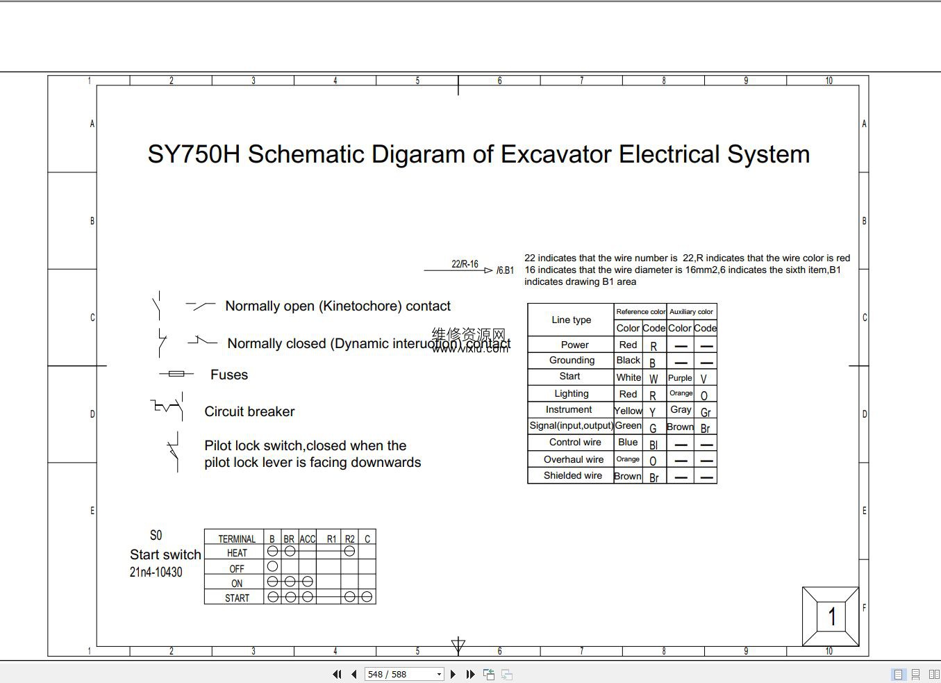
9 Hydraulic & Electrical Diagram
9.1 Symbol Description
9.2 Start and Preheating Control
9.3 Assistant Function Control
9.4 CAN Communication
9.5 Assistant Function Control 2
9.6 Main Controller
9.7 Main Controller 2
9.8 Auxiliary Controller
9.9 Display
9.10 Engine Controller
9.11 AC Control
9.12 Fuse Box
9.13 Cab Harness
9.14 Control Switch Harness
9.15 Tool Box Harness
9.16 Pump Chamber Harness
9.17 Vehicle Body Harness
9.18 Body harness
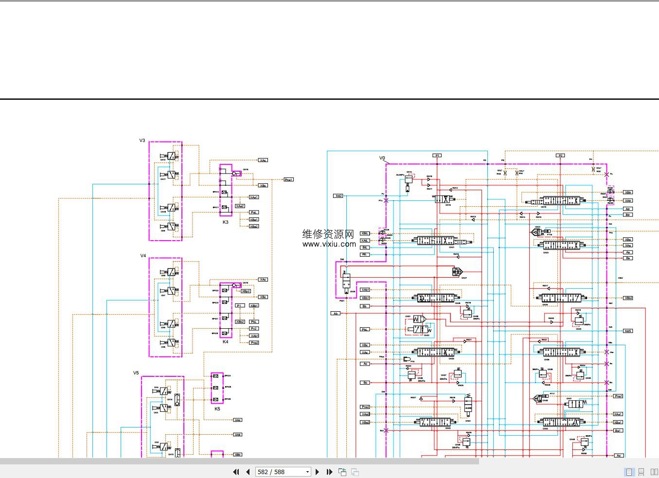
9.19 Hydraulic Schematic Diagram
|
| 资料简介: |
|
|
| 相关资料: |
| |
| 网友评论:(评论内容只代表网友观点,与本站立场无关!) |
|


 [
[

 站内资料搜索